Terminology
Grandmaster clock - the clock that is the main source of time data during synchronization according to the PTP protocol and is usually equipped with a built-in GPS receiver (or another system).
Master clock - a clock that is the source of time data used by other clocks in the network for synchronization. Most often, this is the grandmaster clock.
Slave clock - an end device that synchronizes using the PTP protocol.
Transparent clock - a switch that measures the time a synchronization message spends passing through it, measures link delay, and provides the measured value to the clocks that receive the synchronization message further.
Boundary clock - a clock equipped with multiple PTP ports that can act as a master clock; for example, it can be a slave relative to upstream time sources and act as a master for downstream devices.
Operating modes
End-to-End (E2E)
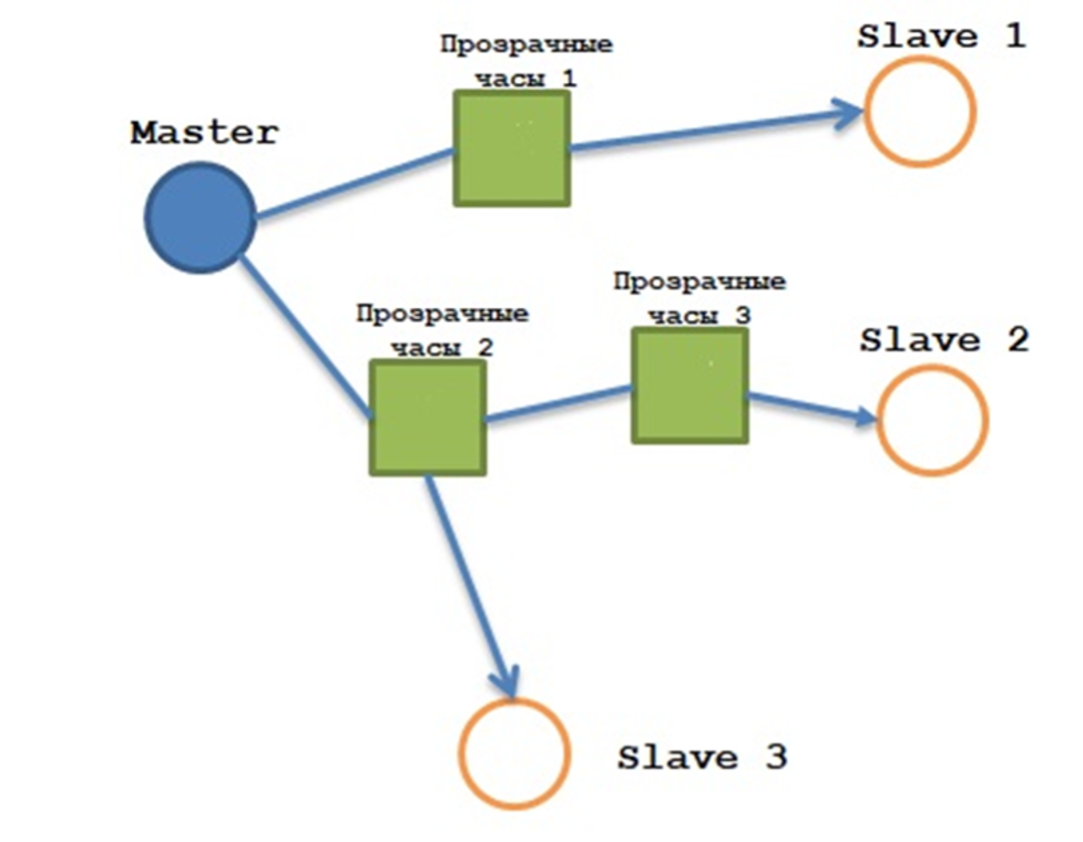
In this mode, network equipment (switches) operates as transparent clocks.
Delay is measured by the master for the entire path from the master to each end device separately.
This implies a disadvantage of this mode: high load on the master.
Peer-to-peer (P2P)
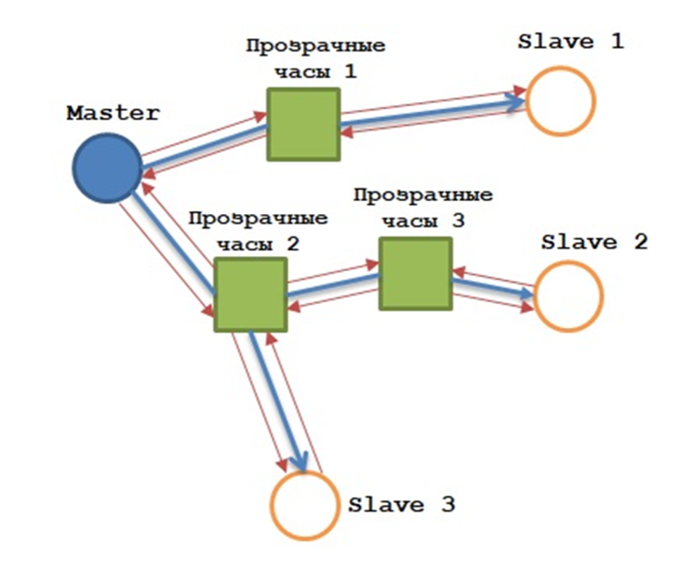
All switches must support P2P.
In this case, switches measure the delay of each of their links in advance (red arrows in the picture), which makes PTP topology rebuilds fast when the topology changes.
Terminology once again
Announce message - an announcement message containing information sent by the master to all slave devices. A slave device can use this message to choose the best master. For this, the BMC (Best Master Clock) algorithm exists. Selection is based on message fields such as accuracy, variance, class, priority, and so on.
Sync/Follow Up, DelayResp - sent by the master.
DelayReq - requests from slave devices.
Field priority for the BMC (Best Master Clock) algorithm:
- priority1: configured by the user, default value 128 (the lower the value, the higher the priority)
- clockClass: depends on error and the number of satellites (class 6 is required for PTP)
- clockAccuracy: accuracy (25 ns, 100 ns, 250 ns, 1 us, 2.5 us, 10 us, 25 us, 100 us, 250 us, 1 ms, 10 s, and > 10 s)
- offsetScaledLogVariance: clock stability
- priority2: configured by the user, default value 128 (the lower the value, the higher the priority)
- MAC Address
E2E operation session
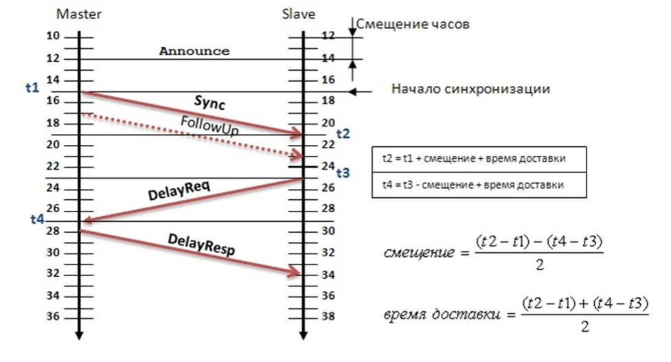
Operating mode:
- At the very beginning, the master sends an Announce message. From all masters, the slave selects the best one.
- The master sends a Sync message and records the send time of this message as t1. There are one-step and two-step operating modes. They are very easy to distinguish: if a FollowUp message is present, it is a two-step implementation; the dashed arrow shows optional messages.
- In two-step mode, the FollowUp message contains t1; in one-step mode, t1 is in the Sync message.
- When the Sync/FollowUp message is received on the slave, t2 is generated.
- The slave generates a DelayReq message and t3 at the same time.
- When the master receives the DelayReq message, t4 is generated.
- The master sends t4 in the DelayResp message.
After receiving t1, t2, t3, and t4, the slave calculates the offset and delivery time, then adjusts time in the Sync message.
P2P operation session
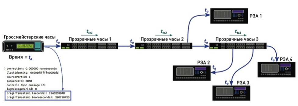
- Sync messages are transmitted unchanged by transparent clocks.
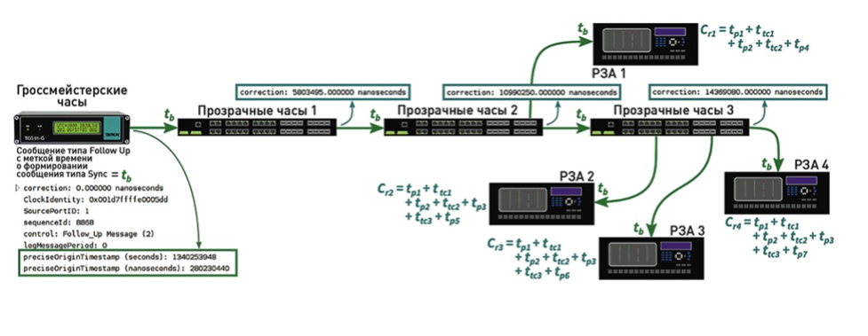
- ta is the time reading on the grandmaster clock. Announce messages are transmitted in the same way.
- Each transparent clock measures the processing time of the Sync message: ttc1.
- Each transparent clock calculates the link delay between neighboring devices: tp1 (figure below).
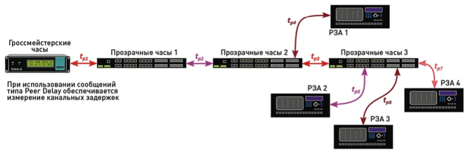
Messages are exchanged bidirectionally between neighboring devices to calculate link delay. The calculation scheme is shown below.
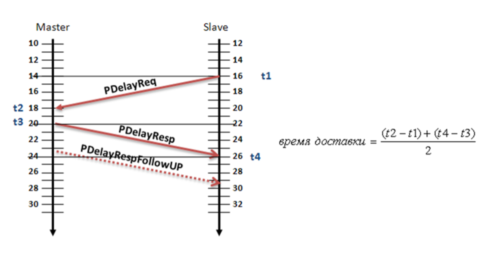
- When a PDelayReq request is sent, t1 is generated.
- When the master receives PDelayReq, time t2 is generated.
- The master sends PdelayResp with time t2.
- The slave receives PdelayResp and generates t4.
- The master sends PdelayRespFollowUP with time t3.
Knowing t1, t2, t3, and t4, the slave (transparent clock) calculates the communication link delay (delivery time).
Now each transparent clock has message processing time (ttc1), link delay time (tp1), and the grandmaster clock time itself (ta).
FollowUp
If two-step mode is used, devices take the grandmaster clock time from FollowUp messages (tb). However, most devices now already support one-step mode.
Transparent clocks receive the grandmaster clock time (ta or tb). Then they add a correction value (ttc1 + tp1) to the correction field.
The next transparent clocks receive the same grandmaster clock time (ta or tb), but already with the correction field filled in, and add the field value to their own delays (ttc2 + tp2). This continues until the endpoint (slave clocks).